
Running high speed (Cat 5, 5e, 6, etc) cable to connect your electronic devices is a dying art thanks to WiFi. But, you may need to make a patch cable at some point in your life. If so, this blog is here to help. 🙂
Two examples you may run into: Our Arlo Pro Security Camera base station uses a fairly long (reaching from the study to the living room) RJ-45 cable to connect to our Orbi WiFi router then to the Internet, and, speaking of the Orbi, the Orbi Wifi router itself connects to the Cable Modem via RJ-45.

You can buy a patch cord to do the job, or, if you want to save a bit of money, you can build one out of spare parts just hanging around in the trunk of your car or house. Oh, wait, you don’t have RJ-45 plugs, an 8 wire crimper or a roll of cat 5, 5e, or 6 cable in the trunk of your car? I thought everyone did? Hmmmmm, scratch that idea. 😉
Anyway……in the old days, I have connected zillions of endpoints and built zillions of my own RJ-45 cables to connect these devices. I do the same today (i.e. conect endpoints), but, I do it wirelessly….sooooo much easier than cable……but, not nearly as much fun.
So……for nostalgia sake, and just in case you need to know how to make an RJ-45 patch cable, this blog exists. FYI….I am now using one of the cables I built here to connect the Orbi to the Internet, the Arlo is already using a Mike special long cable.
Caveat
I am NOT a perfectionist, so what you are about to see is how to build an RJ-45 patch cable for connecting devices in your home or office that is not perfect. It will work, but, may not look pretty, in fact, it may be downright ugly. But who cares? It will work! And look at the hours (minutes) of pleasure you had making it. 🙂
Lets get started
But first….
The TIA/EIA-568B Standard
Way back when dinosaurs ruled the Earth, standards were developed to connect high-speed data devices and networks together in the local area. One standard in particular caught on with most of us (yes, I was there, TriceraMike, BrontosauraMike) and that was the TIA/EIA-568B (there is an “A” version but….B is the important one).

I grabbed that screenshot from Wikipedia. Starting at the top, white/orange is pin 1 and solid brown is pin 8. The telephone tip and ring wires (blue and white/blue) are in the middle, while Tx and Rx pairs for data are the orange pairs and green pairs.
Parts and Tools Needed
This is where you go to the trunk of your car and grab a few spare parts. Category 5, 5e, or 6 (with 7 and 8 on the market now too) wire with 4 pair of solid wire (I hate stranded wire) and a few RJ-45 plugs. For tools, all you need is an 8 pin crimper, a pair of wire cutters, and a knife.

The first thing I do is carefully (so I don’t nick the wires) cut away a couple of inches of the wire covering. Just carefully twist the knife around it to break it a bit, then pull it off. Depending on the wire you have, you will then cut off either a material pull string thingy, or a plastic form holding the wires. The idea is to get the wires all by themselves.
The result looks like this.

Now you can separate the wires into the color groupings.

Then, with a bit of effort, untwist and line up the wires according to the chart above. White/Orange, Orange, White/Green, Blue, White/Blue, Green, White/Brown, Brown. And YES, the green wires are separated by the blue pairs (gotta be compatible with the old telephone systems).
This is what it can look like (yours will certainly be nicer).

What I do next is to make sure the wires are tightly grouped together and the colors are still in the right place. Then I cut them straight across as close to the covering as comfortable. The object there is to shorten the untwisted portion of the wire, to maintain high-speed data compliance, and, also, to make it so the RJ-45 plug grabs the wire covering.
Then you slide the RJ-45 plug, in the direction shown, over the wires. If you have lined the wires up neatly, they “should” slip into the correct slots easily.

Now insert the RJ-45 plug into the 8 pin port of your crimper and squeeeeeze to crimp.

Pull the wire out of the crimper, and you have HALF of your first RJ-45 patch cable. Congratulations! See how easy? 🙂 Now…..repeat for the other side. when you have both sides, you have your first homemade patch cord.

Now you need to test the cable. There are special tools to test the cable, but, I just plug it in and see if it works. It either will or won’t. Fix and Repeat until it works.
Summary
Making an RJ-45 patch cable is a dying art, but, still needed in some cases. In 2019, for the few times in your life moving forward, you may just want to buy a patch cable on Amazon. Truthfully…..I do. they are very high quality and not expensive.
But, if you want to have some fun building your own, just order some parts and follow this blog.
I REALLY did have fun making a few cables and dreaming about the good old days. Interestingly, muscle memory kicked in while I was making the first cable and I zipped through a couple more just like I was at TeleCon building a videoconferencing booth for 20,000 or so conference attendees.
**Sigh**
Geek on!
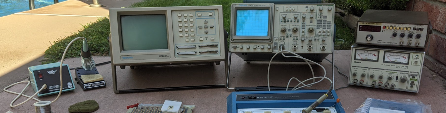
Here is a real blast from the past. Yes this was in the trunk of my car. 🙂
RadioShack. 😦

More GEEK stuff….